- 您现在的位置:买卖IC网 > Sheet目录1196 > ATADAPCAN01 (Atmel)EXTENSION CAN ADD-ON TO STK500/1
�� �
�
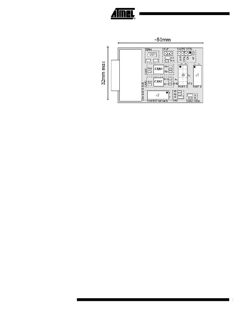
�Figure� 2.� Component� Placement�
�Utilising� CAN-�
�Transceiver� Extra-�
�features�
�Slope� Control� (pin� 8,�
�"CAN1"� and� "CAN2")�
�Standby� Function� (pin� 8,�
�"CAN1"� and� "CAN2")�
�Shutdown� Function�
�(pin� 5,� "CAN2")�
�Split� Voltage� (pin� 5,�
�"CAN1")�
�Many� CAN� transceiver� devices� available� have� various� extra� functions� accessible�
�through� pins� 5� and� 8.� The� ATADAPCAN01� allows� you� to� take� advantage� of� some� of�
�these� features.� Pin� 8� on� both� "CAN1"� and� "CAN2"� footprints� are� connected� centre� pin� of�
�the� "SLOPE� CTRL"� connector.� Pin� 5� of� "CAN1"� is� connected� to� the� centre-tap� of� the� ter-�
�mination� network,� and� pin� 5� of� "CAN2"� is� connected� to� R6� and� C2� as� shown� in� Figure� 2.�
�CAN� transceivers� supporting� slope� or� slew-rate� control� allow� a� resistor� to� be� connected�
�between� the� RS� pin� (pin� 8)� and� ground� to� limit� the� slope� of� the� bus-driving� signal.� This�
�reduced� EMI� emmissions� while� restricting� the� maximum� transmission� rate.� Pin� 8� on� both�
�"CAN1"� and� "CAN2"� devices� are� connected� to� the� centre� pin� of� the� "SLOPE� CTRL"�
�jumper.� Setting� the� jumper� to� the� ON� position,� connects� the� centre� pin� to� ground� through�
�resistor� R7,� while� setting� it� to� the� OFF� position� connects� the� centre� pin� directly� to� ground�
�(for� no� slope� control,� or� high-speed� mode).� Refer� to� the� CAN� transceiver� device� docu-�
�mentation� for� information� on� selecting� the� value� of� R7� (24k� by� default).�
�On� some� CAN� transceivers,� pin� 8� can� be� driven� by� a� logic� level� to� switch� the� transceiver�
�into� standby� mode.� The� centre� pin� of� the� "SLOPE� CTRL"� header� (with� the� jumper�
�removed)� can� be� connected� to� an� I/O� pin� on� the� AVR� device� for� this� purpose.� Your� AVR�
�code� should� drive� this� signal� as� specified� in� the� CAN� transceiver� documentation.�
�Some� CAN� transceivers� have� a� SHUTDOWN� function� which� is� configured� by� an� R-C�
�connection� on� pin� 5.� Pin� 5� of� the� "CAN2"� footprint� is� connected� to� resistor� R6� to� Vcc� and�
�capacitor� C2� to� ground,� as� shown� in� the� schematic� diagram.� By� default� R6� is� a� 0� ohm�
�connection� to� Vcc� and� C2� is� not� mounted.� Both� parts� are� 0603� size.� Consult� the� CAN�
�transceiver� documentation� for� further� information.�
�The� centre-point� of� the� CAN� bus� termination� (if� enabled)� can� be� stabilised� by� connecting�
�it� to� pin� 5� of� certain� CAN� transceivers.� If� the� CAN� transceiver� supports� this� feature,� a� 0�
�ohm� 0603� resistor� can� be� mounted� in� R14,� with� the� "SPLIT"� and� "TERM"� jumpers� set�
�accordingly� (see� Section� ”CAN� bus� termination”).�
�4�
�AT90CAN128�
�4330B–CAN–03/04�
�发布紧急采购,3分钟左右您将得到回复。
相关PDF资料
ATAVRBC100
REF DESIGN KIT BATTERY CHARGER
ATAVRDB101
MODULE DISPLAY LCD/RGB BACKLIGHT
ATAVRMC100
KIT EVALUATION FOR AT90PWM3
ATAVRMC200
KIT EVAL FOR AT90PWM3 ASYNC
ATAVRMC300
BOARD EVAL LV MOTOR CONTROL PWR
ATAVRMC303
BOARD EVAL MOTOR CTRL W/XMEGA
ATAVRMC320
KIT EVAL MOTOR CTRL CAN/LIN
ATAVRSB100
SMART BATTERY DEVELOPMENT KIT
相关代理商/技术参数
ATADAPMEGA162
功能描述:子卡和OEM板 ADAPTER FOR ICE50 MEGA-ATMEGA8515/162 RoHS:否 制造商:BeagleBoard by CircuitCo 产品:BeagleBone LCD4 Boards 用于:BeagleBone - BB-Bone - Open Source Development Kit
ATADAPMEGA169
功能描述:ADAPTER PERSON ICE50 ATMEGA169 RoHS:否 类别:编程器,开发系统 >> 过时/停产零件编号 系列:- 标准包装:1 系列:- 类型:MCU 适用于相关产品:Freescale MC68HC908LJ/LK(80-QFP ZIF 插口) 所含物品:面板、缆线、软件、数据表和用户手册 其它名称:520-1035
ATADAPMEGA32
功能描述:子卡和OEM板 ADAPTER F/ICE50 MEGA ATMEGA8535/16/32 RoHS:否 制造商:BeagleBoard by CircuitCo 产品:BeagleBone LCD4 Boards 用于:BeagleBone - BB-Bone - Open Source Development Kit
ATADAPMEGA8
功能描述:子卡和OEM板 ADAPTER FOR ICE50 MEGA - ATMEGA8 PDIP RoHS:否 制造商:BeagleBoard by CircuitCo 产品:BeagleBone LCD4 Boards 用于:BeagleBone - BB-Bone - Open Source Development Kit
ATADAPT2313
功能描述:子卡和OEM板 ADAPTER FOR ICE50 TINY2313 RoHS:否 制造商:BeagleBoard by CircuitCo 产品:BeagleBone LCD4 Boards 用于:BeagleBone - BB-Bone - Open Source Development Kit
ATADAPTCAN01
制造商:Atmel Corporation 功能描述:STK501 CANN ADD-ON - Bulk
ATADAPTEST
功能描述:子卡和OEM板 ADAPTER FOR ICE50 TEST RoHS:否 制造商:BeagleBoard by CircuitCo 产品:BeagleBone LCD4 Boards 用于:BeagleBone - BB-Bone - Open Source Development Kit
ATADAPTINY13
功能描述:子卡和OEM板 ADAPTER FOR ICE50 TINY13IP
RoHS:否 制造商:BeagleBoard by CircuitCo 产品:BeagleBone LCD4 Boards 用于:BeagleBone - BB-Bone - Open Source Development Kit